N4 supports a truck callup process that involves multiple exchange areas and a staging area for each exchange area. A staging area may also include buffers, allowing trucks to be released to a particular exchange area when all exchange lanes are allocated.
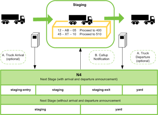
For staging areas, configurations may involve pedestals, display boards, loop detectors, and any possible combination, provided a site has the proper mechanisms to record a truck's arrival and departure. If proper mechanisms are not in place, you can set up the process without arrival and departure recording. The following figure illustrates a possible setup.
The Road Call-up background job executes the callup process. This job periodically scans truck visits at the stage that has been set up as staging stage, decides which trucks can be called up, and executes the on-submit workflow for each selected truck visit. The on-submit workflow may include the SendCallupMessage business task, which executes at the Truck Visit/on-submit (at staging area) timing. It sends an individual callup message to the gate operating system (GOS), including truck details and moves to be performed.
Determining which trucks to call up depends on:
The availability of lanes at each exchange area
The buffer size for the area
The number of trucks waiting for that area
For side-loading exchange areas (Transfer Zone - Transtainer yard block), the buffer size for the particular exchange lane,
The sequence of the waiting trucks
The value of the XPS setting EDLSRD, which determines whether trucks can be called up while the TZ is full
The Road Call-up background job examines the list of waiting trucks by exchange area and sequence number, and it releases trucks in this order, provided that exchange lanes are available, up to the point where available exchange lanes, exchange lane buffer, and exchange area buffer are all fully utilized.
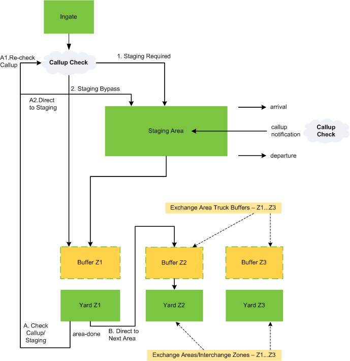
To prevent unnecessary traffic to the staging area at quiet times, N4 allows trucks to bypass the staging area when not necessary. This behavior is based on the SetStagingIfRequired business task.
The following figure illustrates the position of a staging area in the gate flow and possible routes taken. The figure includes three exchange areas. N4 supports an unlimited number of gates and exchange areas. You specify the actual number using the Seq Nbr field in the Gate form and Exchange Areas form, respectively. When a truck completes an exchange area visit, N4 executes the area-done workflow.
End-loading operations
When calculating the exchange area capacity for end-loading operations (with exchange areas of type Transfer Zone - Wheeled or Transfer Zone - Straddle), N4 takes the following variables into account:
Buffer Size = The number of trucks that may still be released to a particular exchange area when all exchange lanes are allocated.
Number of Available Exchange Lanes = Number of lanes in the exchange area that are OPEN and EMPTY.
Trucks Driving = The number of trucks that are assigned to the exchange area but have not yet occupied a lane (still in buffer area).
To calculate an exchange area’s capacity, N4 uses the following formula:
capacity = (Buffer Size) + (Number of available Exchange Lanes) - (Trucks Driving)
The logic to calculate the exchange area’s capacity can also be customized by defining a new code extension of type TRUCK_CALLUP_INTERCEPTOR. This code extension groovy implementation should extend class AbstractTruckCallupInterceptor and override the method exchangeAreaHasCapacity(). Overriding this method lets you define your own criteria to mark an exchange area as having the capacity to serve the truck visit.
In the following example, the buffer size is 5.
When the first truck (T1) comes in for exchange lane A, the N4 callup process allows the truck to move forward to the yard. Because assigned exchange lane A is already available, the truck drives directly to it. At this point, the exchange area buffer has 0 trucks.
When a second truck (T2) arrives for exchange lane A, the N4 callup process allows the truck to move forward to the yard. Because assigned exchange lane A is already occupied by T1, T2 will go to exchange lane B. At this point, the exchange area buffer still has 0 trucks; 2 exchange lanes are now occupied.
When trucks T3, T4, and T5, arrive for exchange lane A, the N4 callup process allows all trucks to move forward to the yard and occupy exchange lanes C, D, and E. All exchange lanes are now occupied, but the buffer still has 5 available lanes.
When trucks T6 –T10 arrive for exchange lane A, the N4 callup process allows all the trucks to move forward to the yard and occupy all lanes in the buffer zone. At this point, all 5 exchange area lanes and all 5 lanes in the buffer zone are occupied.
When truck T11 arrives for exchange lane A, N4 does not allow the truck to move forward to the yard because the capacity at this point is 0.
The cycle continues, and as trucks complete their receival/delivery, trucks waiting in the exchange area buffer can move forward to one of the exchange lanes. This then frees up slots in the exchange area buffer to allow more trucks to be called up. In this example, up to 5 trucks can be waiting in the exchange area buffer at a time.
Side-loading operations
When calculating the exchange area capacity, N4 takes the following variables into account:
Buffer Size of Exchange Area = Size of buffer zone, which is a physical space in the yard where trucks can wait while their assigned exchange lanes free up. Trucks may wait in the buffer zone (if necessary) after they have been released from the staging area.
Buffer Size of Exchange Lane = Total number of trucks assigned to the same exchange lane that are allowed to enter the buffer zone while waiting for their assigned exchange lane to free up.
Trucks Driving to Exchange Area = The total number of trucks that are waiting in the buffer zone of an exchange area. The trucks are assigned to the same exchange lane in the same exchange area.
Availability of Appointed Exchange Lane = Lane status is OPEN and the laneTruck status is EMPTY for both the appointed exchange lane and the adjacent lane(s).
For example, if there are 6 exchange lanes, the traffic direction is ascending (left to right), and the truck chassis is a 40-foot container, the OTR needs 3 rows to park: 1 row for the cab and 2 rows for the chassis. In this case, if the truck's appointed exchange lane is lane:
3, N4 checks if lanes 3, 4, and 5 are available.
5, N4 checks if lanes 5 and 6 are available.
6, N4 only checks if lane 6 is available.
To calculate an exchange area's capacity, N4 uses the following formula: If laneBufferSize > 0 AND laneBufferSize < areabufferSize, then capacity = laneBufferSize + exchangeLaneAvailability - trucksDriving; otherwise, capacity = areabufferSize + exchangeLaneAvailability - trucksDriving.
The logic to calculate the capacity of an exchange area of type Transfer Zone – Transtainer can also be customized by defining a new code extension of type TRUCK_CALLUP_INTERCEPTOR. This code extension should extend class AbstractTruckCallupInterceptor and override the method transtainerExchangeAreaHasCapacity(). Overriding this method lets you define your own criteria to mark a Transfer Zone - Transtainer exchange area as having the capacity to serve the truck visit. For more information, see Customize how N4 determines exchange lane capacity.
Following is a side-loading example (for an exchange area of type Transfer Zone - Transtainer) where the buffer size is 5 and the exchange lane buffer size is 1.
When the first truck (T1) comes in for exchange lane A, the N4 callup process allows the truck to move forward to the yard. Because appointed exchange lane A is already available, the truck drives directly to it. At this point, the exchange area buffer has 0 trucks.
When a second truck (T2) arrives for exchange lane A, the N4 callup process allows the truck to move forward to the yard. Because appointed exchange lane A is already occupied by T1, T2 will wait in the exchange area buffer. Now the exchange area buffer has 1 truck.
When a third truck (T3) arrives for exchange lane A, the N4 callup process does not allow the truck to move forward to the yard because only 1 truck heading for exchange lane A can wait in the exchange area buffer at a time.
When a forth truck (T4) arrives for exchange lane B, the N4 callup process allows the truck to move forward to the yard. Because appointed exchange lane B is already available, the truck drives directly to it.
T1 is still occupying exchange lane A, so the total number of trucks in the exchange area buffer is still 1 (T2).
When a fifth truck (T5) arrives for exchange lane B, the N4 callup process allows the truck to move forward to the yard. Because appointed exchange lane B is already occupied by T4, T5 will wait in the exchange area buffer. Now the exchange area buffer has 2 trucks.
The cycle continues, and as trucks complete their receival/delivery, trucks waiting in the exchange area buffer can move forward to the appointed exchange lane. This then frees up slots in the exchange area buffer to allow more trucks to be called up. In this example, up to 5 trucks can be waiting in the exchange area buffer at a time.
Callup process setup
To configure a truck callup process with staging areas:
In the Gate form, configure the sequence of gates for a truck visit in the Seq Nbr field.
In the Gate Stage form (on page 1), configure a truck staging area by selecting the Supports Callup check box to indicate that the callup gate stage is the 'staging' stage.
In N4, staging areas are modeled as gate stages that support truck callup.
In the Exchange Areas view (on page 1), use the Exchange Area form (on page 1) to configure exchange areas by setting up sequence number, TEU, and buffer size information. This includes setting:
The Buffer Size for the exchange area, which is the size of the buffer zone area (a physical space in the yard where trucks can wait while their assigned exchange lane queue frees up).
The Exchange Lane Buffer Size (only needed when setting up side-loading transfer zones), which is the number of trucks that may still be release to a particular lane queue before N4 stops sending trucks to their assigned exchange lane. When the number of trucks in the queue exceeds the specified value, N4 instructs trucks to wait in the staging area.
The value entered here applies to all lanes in a particular exchange area.
In the Lanes view (on page 1), use the Exchange Lane form (on page 1) to configure the lanes for each exchange area. This includes setting:
The Assignment Priority for exchange lane assignment (optional). You can also set how N4 sequences the transactions and assigns exchange lanes using the business tasks.
The Clearance Delay for the exchange lane (optional).
Repeat steps 3 and 4 for every exchange area.
In the Settings view, configure the following settings:
ROADCALLUP001 (on page 1): To specify the callup interval.
ROADCALLUP002 (on page 1): To specify the Web Service URL.
In your gate configuration, include and configure the following business tasks for the respective exchange areas:
AssignExchangeLane (on page 1) or AssignExchangeLaneIfReady (on page 1) and SequenceTransactions (on page 1): To determine when N4 assigns exchange lanes and the sequencing of lane assignments.
SetDefaultExchangeArea (on page 1): To specify the default exchange area in the ExchangeAreaId parameter.
RejectNoExchangeArea (on page 1) (optional): To reject a gate transaction if no exchange area is assigned.
RejectWrongExchangeArea (on page 1) (optional): To prevent a truck from registering in the wrong exchange lane.
AdvanceTruckToStage (on page 1): To advance trucks expected at an earlier gate stage, such as trucks that skip the staging area during quiet times and are sent directly to the yard stage.
CheckTruckOKAtStage (on page 1): To check that the truck is OK for processing at a gate stage before creating the truck visit.
MaintainAreaStats (on page 1): To recompute the figures for trucks queued and staged when a truck executes its configured timing point.
RecordLaneMission (on page 1): To populate the Mission field in the Gate Exchange Area Monitor view with a list of containers to be handled at that stage.
SendCallupMessage (on page 1): To notify the gate operating system (GOS) about truck callups.
SetStagingIfRequired (on page 1): To evaluate the staging requirements at the gate. If staging is required, the truck is sent to the staging area.
Customize the callup process if needed:
Override gate tasks at their entry or exit points by defining a new code extension of type GATE_WORKFLOW_INTERCEPTOR.
Override parts or all of the callup process by defining a new code extension of type TRUCK_CALLUP_INTERCEPTOR.
Override the callup message process by defining a new code extension of type SEND_TRUCK_CALLUP_MSG_INTERCEPTOR to customize message content and message delivery for the SendCallupMessage business task.
Customize how N4 selects the appointed exchange lane by defining a code extension of type TRANSACTION_EXCHANGE_LANE_SELECTOR_INTERCEPTOR.
In the Background Jobs view, select Actions  Launch Road Call-Up.